The next question you would probably ask is, so which one should I choose? Which is the best? Unfortunately the answer isnt that simple. It depends on many factors and even among experts there is no consensus on this matter. So, we wont try to answer this question here. But what I would try, is to give a general idea on the various types of reset which will help you make the best decision suitable for your project.
1. Purely Synchronous Reset:
A synchronous reset signal can be coded in VHDL as shown below :
library ieee;
use ieee.std_logic_1164.all;

entity sync_reset is
port(clk : in std_logic;  --clock
    reset : in std_logic; --active high reset
    in_bit : in std_logic;
    out_bit_sync : out std_logic
);
end sync_reset;

architecture Behavioral of sync_reset is

begin

process(clk)
begin
    if(rising_edge(clk)) then
        if(reset = '1') then  --reset is checked only at the rising edge of clock.
            out_bit_sync <= '0';
        else
            out_bit_sync <= in_bit;
        end if;
    end if;
end process;

end Behavioral;
You can see that the value of reset input is only checked at the rising edge of the clock signal. That is why it is called a synchronous reset. Look at the below simulation waveform from Modelsim to get a better understanding of the code.
The in_bit is sampled only at the rising edge of the clock cycle. The short reset pulse is ignored because it didnt align with any of the rising edges of the clock. The reset signal was asserted again, but it wasnt sampled until the next rising edge of the clock, upon which the output bit was set to '0'.
When synthesised, Xilinx Vivado tool generated the following schematic for the above code:

Ignoring the buffers for inputs and output, the tool uses a single flipflop, FDRE for implementing this code. Xilinx doc on FDRE says:
FDRE is a single D-type flip-flop with data (D), clock enable (CE), and synchronous reset (R) inputs and data output (Q). The synchronous reset (R) input, when High, overrides all other inputs and resets the (Q) output Low on the Low-to-High clock (C) transition. The data on the (D) input is loaded into the flip-flop when R is Low and CE is High during the Low-to-High clock transition.
Now, lets look into the pros and cons of this(synchronous reset) approach.
Pros
- The reset applied to all the flip-flops are fully synchronized with clock and always meet the reset recovery time. Reset recovery time is the minimum time between the de-assertion of a reset and the clock signal being high again.
- In some cases, synchronous resets will reduce the number of flipflops used at the expense of combinational logic gates. So this may not be truly an advantageous point.
Cons
- If the reset pulse is not wide enough then the clock edge may not be able to capture the reset signal. Thus, if you use synchronous resets make sure that your reset signal stays active for enough time so that it gets captured by the clock.
- The change in reset input doesn't immediately reflect in the signals which are to be reset.
- Synchronous resets have high fan-outs. Fan-out refers to the maximum number of output signals that are fed by the output equations of a logic cell. High fan-out makes it difficult to meet timing constraints without pipelining and duplicating the synchronous reset source.
- Synchronous resets, by their very nature, needs a clock in order to work. This can be annoying, for example, if you are using a gated clock. As the reset will go unregistered if the reset is asserted, when the clock is disabled to save power.
2. Purely Asynchronous Reset:
An asynchronous reset signal can be coded in VHDL as shown below :
library ieee;
use ieee.std_logic_1164.all;

entity async_reset is
port(clk : in std_logic;  --clock
    reset : in std_logic; --active high reset
    in_bit : in std_logic;
    out_bit_async : out std_logic
);
end async_reset;

architecture Behavioral of async_reset is

begin

process(clk,reset)
begin
    if(reset = '1') then  --change in reset get immediately reflected on output
        out_bit_async <= '0';
    elsif(rising_edge(clk)) then
        out_bit_async <= in_bit;
    end if;
end process;

end Behavioral;
You can see that the value of reset input is checked irrespective of any event from the clock signal. That is why this is called a asynchronous reset. Look at the below simulation waveform from Modelsim to get a better understanding of the code.

You can see that, contrary to the first simulation, the reset takes effect immediately and sets the output bit to '0'.
When synthesised, Xilinx Vivado tool generated the following schematic for the above code:

Ignoring the buffers for inputs and output, the tool uses a single flipflop, FDCE for implementing this code. Xilinx doc on FDCE says:
FDCE is a single D-type flip-flop with clock enable and asynchronous clear.
- When clock enable (CE) is High and asynchronous clear (CLR) is Low, the data on the data input (D) of this design element is transferred to the corresponding data output (Q) during the Low-to-High clock (C) transition.
- When CLR is High, it overrides all other inputs and resets the data output (Q) Low.
- When CE is Low, clock transitions are ignored.
Now, lets look into the pros and cons of this(Asynchronous reset) approach.
Pros
- Signals can be reset without waiting for the clock edge to arrive. Or in general, the clock needn't even be there.
- If the FPGA vendor library has asynchronously resettable flip flops then the data path will be clean. This is because there is no need to place any extra logic gates on the data-path to implement the reset.
Cons
- If the asynchronous reset is released at or near the active clock edge of a flip-flop, the output of the flip-flop could go metastable and thus the reset state could be lost. This is not so much of a dangerous issue on assertion of reset, but could be disastrous at de-assertion.
- Depending on the source, sometimes resets may occur spuriously due to noise or glitches on the board or system reset. All such events will be counted as valid resets.
3. Asynchronous Assertion, Synchronous De-assertion:
We can assert the reset synchronously and de-assert it asynchronously. Such a circuit is called a reset synchronizer. Let us see how this can be done in VHDL:
library ieee; use ieee.std_logic_1164.all; entity reset_synchronizer is port(clk : in std_logic; --clock reset : in std_logic; --active high reset in_bit : in std_logic; out_bit : out std_logic ); end reset_synchronizer; architecture Behavioral of reset_synchronizer is signal rst_local, temp : std_logic; begin--create a local reset from reset inputprocess(clk,reset) begin if(reset = '1') then --assert reset asynchronously temp <= '1'; rst_local <= '1'; elsif(rising_edge(clk)) then --deassert reset synchronously temp <= '0'; rst_local <= temp; end if; end process;--use the local reset generated to manipulate the main logicprocess(clk,rst_local) begin if(rst_local = '1') then --local reset is used to reset the output out_bit <= '0'; elsif(rising_edge(clk)) then out_bit <= in_bit; end if; end process; end Behavioral;
We use two processes to implement this circuit. First process generates a local reset signal called rst_local and the second process uses the generated local reset and clock to implement the desired logic.
When the reset is just asserted, the local reset immediately follows it, but when its de-asserted, it has to travel through two D flipflops to be reflected in the local reset. What is the use of this? This means that, the reset we use locally, stays for one whole clock cycle before its de-asserted and it wont de-assert just before a clock's positive edge. This resolves a major disadvantage of asynchronous resets.
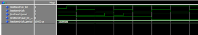
Look at the below simulation waveform from Modelsim to get a better understanding of the code. You can see that how the output bit changes right away when the reset is asserted, but takes at least one clock cycle to change when its de-asserted.

When synthesised, Xilinx Vivado tool generated the following schematic for the above code:
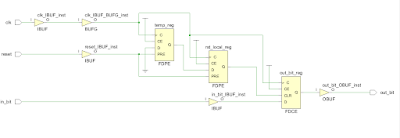
Ignoring the buffers for inputs and output, the tool uses 3 flipflops - two FDPE's(used for generating the local reset) and one FDCE(used for the main logic).
If you scroll up you can see that FDCE was used for implementing asynchronous reset. FDCE has an asynchronous clear input. This clear input is driven from the Q output of the second FDPE flip flop.
What is FDPE? It is a single D-type flip-flop with data (D), clock enable (CE), and asynchronous preset (PRE) inputs and data output (Q). The asynchronous PRE, when High, overrides all other inputs and sets the (Q) output High. The PRE input of FDPE flipflop is connected to the reset input to the design. First flip flop's D input is connected to '0' and its Q is connected to D of the second flipflop. This makes the reset travel through the flipflops when its de-asserted.
Now, lets look into the pros and cons of this approach.
Pros
- The circuit doesn't have metastability problems.
- The circuit can be reset right away, without waiting for the clock edge to arrive.
Cons
- Once the reset is de-asserted, it still takes a minimum of one clock cycle for the system to come out of reset-state.
- Depending on the source, sometimes resets may occur spuriously due to noise or glitches on the board or system reset. All such events will be counted as valid resets.
- Similar to synchronous resets, this type of resets wont always work with gated clocks. The reset will go unregistered, if the reset is asserted when the clock is disabled to save power.
References:-
- Asynchronous & Synchronous Reset Design Techniques
- Get Smart About Reset: Think Local, Not Global (WP272)
Conclusion:-
As stated in the beginning of this post, there is no single approach that works best for all scenarios when it comes to resets. Lay down the characteristics of your system, look into what resources are available in the FPGA you are targeting and then decide what suits your design best.
Happy resetting! :)


the other advantage to synchronous resets is that the synchronous set (for FPGAs) can now be used by logic. Xilinx has a whitepaper on this.
ReplyDeletea large disadvantage is that it is a large net, and can limit clock rate unless pipelined. This can be an issue for coregen/other IP.
some elements, like DSP48's, only have sync resets.
Does someone know about the difference in term of ressouces used for the synchronous et asynchrounous process?
ReplyDeletecan you interface adc804 and papilio one and then give output to a 16*2 lcd
ReplyDelete