VHDL coding tips and tricks: March 2010

Wednesday, March 31, 2010

Reading and Writing files in VHDL - An easy way of testing design

      If your design has a large array of inputs then you cannot put them in the testbench program.It will make the testbench code very difficult to read.In such cases it is advisable to store the inputs in a text file and read it from that file.Even you can have an output file,where you can store your output values.

     In the example I have shown,I have two files.First one is named as "1.txt" and is my input file.The values will be read from this file and simply copied to the second file named "2.txt". The example is meant for just a basic introduction for file handling in VHDL.There are pretty large number of options when it comes to file handling,but I will post them in future.

--include this library for file handling in VHDL.
library std;
use std.textio.all;  --include package textio.vhd

--entity declaration
entity filehandle is
end filehandle;

--architecture definition
architecture Behavioral of filehandle is
--period of clock,bit for indicating end of file.
signal clock,endoffile : bit := '0';
--data read from the file.
signal    dataread : real;
--data to be saved into the output file.
signal    datatosave : real;
--line number of the file read or written.
signal    linenumber : integer:=1;

begin


clock <= not (clock) after 1 ns;    --clock with time period 2 ns


--read process
reading :
process
    file   infile    : text is in  "1.txt";   --declare input file
    variable  inline    : line; --line number declaration
    variable  dataread1    : real;
begin
wait until clock = '1' and clock'event;
if (not endfile(infile)) then   --checking the "END OF FILE" is not reached.
readline(infile, inline);       --reading a line from the file.
  --reading the data from the line and putting it in a real type variable.
read(inline, dataread1);
dataread <=dataread1;   --put the value available in variable in a signal.
else
endoffile <='1';         --set signal to tell end of file read file is reached.
end if;

end process reading;

--write process
writing :
process
    file      outfile  : text is out "2.txt";  --declare output file
    variable  outline  : line;   --line number declaration  
begin
wait until clock = '0' and clock'event;
if(endoffile='0') then   --if the file end is not reached.
--write(linenumber,value(real type),justified(side),field(width),digits(natural));
write(outline, dataread, right, 16, 12);
-- write line to external file.
writeline(outfile, outline);
linenumber <= linenumber + 1;
else
null;
end if;

end process writing;

end Behavioral;

The contents of files 1.txt and 2.txt are shown below:


Now let us discuss about the textio.vhd package and its general features.

It offers the following new data types:


type LINE is access STRING;  -- A LINE is a pointer to a STRING value
type TEXT is file of STRING; -- A file of variable-length ASCII records.
type SIDE is (RIGHT, LEFT);   -- For justifying output data within fields.
subtype WIDTH is NATURAL;     -- For specifying widths of  output fields.

It offers a large number of functions to read and write to a file.You can see the list of all functions and the arguments used here.

In the example program given above I have two different processes,one for reading from the file and another for writing into the file.
endfile() is a function which is used to check whether the end of the file is reached.It returns a '1' when end of file is reached.
The data cannot be read directly into a signal.That is why I have first read it into a variable and then assigned it into a signal.
Every time you write something into the file or read something from the file,the line number is internally incremented.

Note :- One advantage of file handling in VHDL is that,you can test a large number of input combinations for checking the integrity of your design.Sometimes the automatically generated test cases(with the help of a program) can be easily used without much changes in the testbench code.

Monday, March 29, 2010

How to test your design without writing a seperate test bench program?

      Once you have finished writing code for your design,you need to test whether it is working or not.Usually this is done by writing a testbench code.Your module to be tested ( known as UUT - Unit Under Test) is declared as a component in this testbench code and inputs are set with required timings.
      So everything is fine.You just write a testbench code for your design and simulate.Verify the results.Now what is this article about?One disadvantage of the above method is that you need to write lot of unnecessary code in the form of component initiation,signal declarations etc., for testing your design.Testbench code also needs a new file.For big modules this is fine.But what if you are just playing around with VHDL and needs to test arbitrary designs with different input and output formats.Then writing different testbench files for each of them will definitly waste your time.
      So for small codes,you can put your testbench code in your main design file.I have explained it with the help of "counter" example given here.The code is divided by comment lines so that you can get a good overview of what I have done.

-------------------------Library declarations are not changed
library IEEE;
use IEEE.STD_LOGIC_1164.ALL;
use IEEE.STD_LOGIC_ARITH.ALL;
use IEEE.STD_LOGIC_UNSIGNED.ALL;
--------------------------------------------

entity test is
------------------------Port declaration Taken out from original code.
--port (clk : in std_logic;
--      count : out std_logic_vector(3 downto 0);
--     reset :in std_logic
--     );
--------------------------------------------
end test;

architecture Behavioral of test is
signal c : std_logic_vector(3 downto 0) :=(others => '0');
-------------------------new signals are added here
   constant clk_period : time := 1 ns;     --time period of clk.
        --declare the inputs and outputs of your design as signals.
   signal clk : std_logic := '0';
   signal reset : std_logic := '0';
   signal count : std_logic_vector(3 downto 0);
---------------------------------------------------    
begin

----------------------------process for generating clock.
   clk_process :process
   begin
        clk <= '0';
        wait for clk_period/2;
        clk <= '1';
        wait for clk_period/2;
   end process;
--------------------------------------End of clock generation

----------------------Simulation process(Set inputs here)
  stim_proc: process
   begin      
        wait for 7 ns;
        reset <='1';
        wait for 3 ns;
        reset <='0';
        wait for 17 ns;
        reset <= '1';
        wait for 1 ns;
        reset <= '0';
        wait;
  end process;
--------------------------End of simulation process

-------------------------Here comes your original code.  
count <= c;

process(clk,reset)
begin
if(clk'event and clk='1') then
if(c = "1111") then
c <="0000";
end if;
c <= c+'1';
end if;
if(reset='1') then
c <=(others => '0');
end if;
end process;

end Behavioral;

    The changes I have made are :
1) Your entity doesnt have any input or output declarations.
2)All your original inputs and outputs are declared as signals in the code.
3)If your design is clock driven then declare a constant for period of clock as follows:
        constant clk_period : time := 1 ns;     --time period of clk= 1ns.
4)Write the indicated code for clock generation process.
5)Define another process for applying the simulation inputs with proper timing.The contents of this process depends upon the logic you want to test and the test values.
6)Finally your original code is pasted as shown.
    

Fixed Point Operations in VHDL : Tutorial Series Part 3

     This article is a continuation of the tutorial series on fixed_pkg library.In this article I will talk about,arithmetical operations on fixed point signals.I assume that you have read Part 1 and Part 2 of the series.

     If you have gone through Part 2 of the series then you must have seen that assigning a signal results in rounding off the value if the range of the output signal is not sufficient.Yes,this is a great advantage of fixed_pkg.It is designed so that there is no possibility of an overflow.This is different from "numeric_std" library which simply neglect the underflow and overflow bits.In order to make sure that overflow doesn't happen we have to carefully design the size of output signals based on input signal size and the operation performed.The following table shows the Results range for different kind of operations:


    In the table A'left means the left most array index and A'right means the right most array index.The functions max and min are defined as follows:

max(a,b) = a if a > b else b.
min(a,b) = a if a < b else b.

The operations supported by the package for unsigned types are:
+, –, *, /, rem, mod, =, /=, <, >, >=, <=, sll, srl, rol, ror, sla, sra.

The operations supported by the package for signed types are:
+, –, *, /, rem, mod, =, /=, <, >, >=, <=, sll, srl, rol, ror, sla, sra, abs, - (unary).

 Without going much into the explanations I will directly explain their use with the help of some examples. 

Examples for addition:
signal n1,n2 : ufixed(4 downto -3);
signal n3 : ufixed(5 downto -3);
begin
n1 <=  to_ufixed (5.75,n1);     -- n1 = "00101110" = 5.75
n2 <=  to_ufixed (6.5,n2);      -- n2 = "00110100" = 6.5
n3 <= n1+n2;                   -- n3 = "001100010" = 12.25
--See that the range of 'n3' is 5 downto -3 but that of 'n1' and 'n2' is 4 downto -3.

If the range of n3 is 4 downto -3 then the result will be:
n3 = "00110001" = 6.125.
So it is very important to declare the output signal ranges as per the above table.

--For signed numbers:
signal s1,s2 : sfixed(4 downto -3);
signal s3 : sfixed(5 downto -3);
s1 <=  to_sfixed (5.75,s1);     -- s1 = "00101110" = 5.75
s2 <=  to_sfixed (-6.5,s2);     -- s2 = "11001100" = -6.5
s3 <= s1+s2;                   -- s3 = "111111010" = -0.75

Examples for Subtraction:
n1 <=  to_ufixed (5.75,n1);      -- n1 = "00101110" = 5.75
n2 <=  to_ufixed (6.5,n2);       -- n2 = "00110100" = 6.5
n3 <= n2-n1;                    -- n3 = "000000110" = 0.75    

s1 <=  to_sfixed (5.75,s1);      -- s1 = "00101110" = 5.75
s2 <=  to_sfixed (-6.5,s2);      -- s2 = "11001100" = -6.5
s3 <= s2-s1;                    -- s3 = "110011110" = -12.25

Examples for multiplication:
signal n1,n2 : ufixed(4 downto -3);
signal n3 : ufixed(9 downto -6);

signal s1,s2,s3 : sfixed(4 downto -3);
signal s4,s5 : sfixed(9 downto -6);

n1 <=  to_ufixed (5.75,n1);         -- n1 = "00101110" = 5.75
n2 <=  to_ufixed (6.5,n2);          -- n2 = "00110100" = 6.5
n3 <= n2*n1;                        -- n3 = "0000100101011000" = 37.375

s1 <=  to_sfixed (5.75,s1);         -- s1 = "00101110" = 5.75
s2 <=  to_sfixed (-6.5,s2);         -- s2 = "11001100" = -6.5
s4 <= s2*s1;                        -- s4 = "1111011010101000" = -37.375

s3 <=  to_sfixed (-5.75,s1);        -- s3 = "11010010" = -5.75
s5 <= s3*s2;                        -- s5 = "0000100101011000" = 37.375

Examples for Remainder:
signal n1 : ufixed(4 downto -3);
signal n2 : ufixed(2 downto -4);
signal n3 : ufixed(2 downto -3);     -- see how range of n3 is declared here.

signal s1 : sfixed(4 downto -3);
signal s2 : sfixed(2 downto -4);
signal s3 : sfixed(2 downto -3);     -- see how range of s3 is declared here.

n1 <=  to_ufixed (7.25,n1);        -- n1 = "00111010" = 7.25
n2 <=  to_ufixed (1.5,n2);         -- n2 = "0011000" = 1.5
n3 <= n1 rem n2;                   -- n3 = "001010" = 1.25

s1 <=  to_sfixed (-7.25,s1);       -- s1 = "11000110" = -7.25
s2 <=  to_sfixed (-1.5,s2);        -- s2 = "1101000" = -1.5
s3 <= s1 rem s2;                   -- s3 = "110110" = -1.25


Examples for division:
signal n1 : ufixed(4 downto -3);
signal n2 : ufixed(2 downto -4);
signal n3 : ufixed(8 downto -6);     -- see how range of n3 is declared here.

signal s1 : sfixed(4 downto -3);
signal s2 : sfixed(2 downto -4);
signal s3 : sfixed(9 downto -5);     -- see how range of s3 is declared here.

n1 <=  to_ufixed (6.75,n1);          -- n1 = "00110110" = 6.75
n2 <=  to_ufixed (1.5,n2);           -- n2 = "0011000" = 1.5
n3 <= n1 / n2;                       -- n3 = "000000100100000" = 1.5

s1 <=  to_sfixed (-6.75,s1);         -- s1 = "11001010" = -6.75
s2 <=  to_sfixed (1.5,s2);           -- s2 = "0011000" = 1.5
s3 <= s1 / s2;                       -- s3 = "111111101110000" = -1.5

     These are only a few of the operators available in the package.In the next part of the tutorial, I will explain the use of some more operators with example.
Read Part 1 and Part 2 of the series here:
Fixed Point Operations in VHDL : Tutorial Series Part 1
Fixed Point Operations in VHDL : Tutorial Series Part 2

Sunday, March 28, 2010

4 bit Synchronous UP counter(with reset) using JK flip-flops

Here is the code for 4 bit Synchronous UP counter.The module uses positive edge triggered JK flip flops for the counter.The counter has also a reset input.The JK flipflop code used is from my previous blog.For simulating this counter code,copy and paste the JK flipflop code available at the above link in a file and store the file in the same directory with other .vhd files.
The top module code is given below:


--libraries to be used are specified here
library IEEE;
use IEEE.STD_LOGIC_1164.ALL;

--entity declaration with port definitions
entity syn_count4 is
port ( clk:     in std_logic;
          reset:      in std_logic;
          counter : out std_logic_vector(3 downto 0)
);
end syn_count4;

--architecture of entity
architecture Behavioral of syn_count4 is
--signal declaration.
signal J3,J4,Q1,Q2,Q3,Q4,Qbar1,Qbar2,Qbar3,Qbar4 : std_logic :='0';

begin 
J3 <= Q1 and Q2;
J4<= J3 and Q3;
--entity instantiations
FF1 : entity work.JK_Flipflop port map (clk,'1','1',Q1,Qbar1,reset);
FF2 : entity work.JK_Flipflop port map (clk,Q1,Q1,Q2,Qbar2,reset);
FF3 : entity work.JK_Flipflop port map (clk,J3,J3,Q3,Qbar3,reset);
FF4 : entity work.JK_Flipflop port map (clk,J4,J4,Q4,Qbar4,reset);
counter <= Q4 & Q3 & Q2 & Q1;

end Behavioral;

The test bench program used for testing the design is given below:

--libraries to be used are specified here
library IEEE;
use IEEE.STD_LOGIC_1164.ALL;

entity testbench is
end testbench;

architecture behavior of testbench is
--Signal declarations
signal clk,reset : std_logic := '0';
signal counter : std_logic_vector(3 downto 0):="0000";
-- Clock period definitions
constant clk_period : time := 1 ns;

begin
-- Instantiate the Unit Under Test (UUT)
UUT : entity work.syn_count4 port map (clk,reset,counter);

-- Clock process definitions
clk_process :process
begin
        clk <= '0';
        wait for clk_period/2;
        clk <= '1';
        wait for clk_period/2;
end process;

-- Stimulus process
stim_proc: process
begin        
wait for clk_period*20;
reset <='1';
wait for clk_period*2;
reset <='0';
end process;

end;

   The simulated waveform is shown below.Note that when reset is '1' the counter value is reset to "0000" and remains zero till the reset input equals to '0' again.
The code was synthesized using XILINX ISE XST . The RTL schematic of the design is shown below:
Note :- Use RTL Viewer to get a closer look on how your design is implemented in hardware.

Fixed Point Operations in VHDL : Tutorial Series Part 2

     This article is a continuation of the tutorial series on fixed_pkg library.In this article I will talk about, type conversions and assignments of signals of the fixed point data type.I assume that you have read Part 1 of the series.
Let us see how a signal assignment is made.Suppose I have a signal of unsigned fixed point type.I can assign a value (say 9.75 ) in the following way:

signal n1 : ufixed(4 downto -3);
n1 <= to_ufixed (9.75,4,-3);   -- n1 ="01001110"

Here TO_UFIXED is the conversion function used to convert the value "9.75" to binary number in the prescribed range.For a signed number you can use the function "TO_SFIXED".

--an example for TO_SFIXED.
signal n2 : sfixed(4 downto -3);
n1 <= to_sfixed (-9.75,4,-3);  -- n2 = "10110010"

Assignments can be made in a different way also.This is done by using a signal name as a parameter, instead of actual range values.

--Both n1 and n3 contains the same value.
signal n1,n2,n3 : ufixed(4 downto -3);
n1 <= to_ufixed (9.75,n1);   -- n1 ="01001110"
n3 <= to_ufixed (9.75,n2);   -- n3 ="01001110"
Another method of type conversion is by using signal_name'high and signal_name'low attributes.See the below example.
--Type conversion using attributes.
signal n1,n2,n3 : ufixed(4 downto -3);
n1 <= to_ufixed (9.75,n1'high,n1'low);   -- n1 ="01001110"
n3 <= to_ufixed (9.75,n2'high,n2'low);   -- n3 ="01001110"

All the above methods applies equally to TO_SFIXED conversion function also.
Another useful function available in fixed_pkg is resize().This function is used to fix the size of the output.But while changing the size of the output the signal value may get rounded off or get saturated.


--An example for resize() function.
signal n1 : ufixed(4 downto -3);
signal n2 : ufixed(5 downto -5);
n1 <=  to_ufixed (9.75,n2);   -- n1 = "01001110"
n2 <= resize(n1,n2);          -- n2 ="00100111000"

--Resizing functions can be called in the following ways also:
--Method 1
n2 <= resize(n1,n2'high,n2'low);
--Method 2
n2 <= resize(n1,5,-5);

Take the following statements.
n2 <=  to_ufixed (31.75,n2);      -- n2 ="01111111000"  
n1 <= resize(n2,n1);              -- n1 = "11111110"
In the above code snippet the values are assigned without any rounding off because the value "31.75" matched with the range of 'n1'.
Now take the next two statements:
n2 <=  to_ufixed (32.75,n2);      -- n2 ="10000011000"  
n1 <= resize(n2,n1);              -- n1 = "11111111" 
Here the range of 'n1' is not sufficient for the value "32.75",so while resizing it we got all 1's in the output.While writing your code, you should take care of such things.

Note :- Beware of the following type of assignments:

signal n1 : ufixed(4 downto -3);
signal n2 : ufixed(3 downto -4);
n1 <=  to_ufixed (5.75,n1);      -- n1 = "00101110" = 5.75
n4 <= n1;                                -- n4 = "00101110" = 2.875 
    
     Here the compiler will not show any error or warning on 4th line because the size and type of both the signals are same.But as you can see this is not what we expected.Take care while writing your code using fixed_pkg.You may get unexpected results even if you are careless about a single line of code.

Positive edge triggered JK Flip Flop with reset input

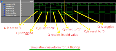
    Here is the code for JK Flip flop which is positive edge triggered.The flip flop also has a reset input which when set to '1' makes the output Q as '0' and Qbar as '1'.


--libraries to be used are specified here
library IEEE;
use IEEE.STD_LOGIC_1164.ALL;

--entity declaration with port definitions
entity JK_Flipflop is
port ( clk:     in std_logic;
          J, K:               in std_logic;
          Q, Qbar:       out std_logic;
           reset:              in std_logic
);
end JK_Flipflop;

--architecture of entity
architecture Behavioral of JK_Flipflop is
--signal declaration.
signal qtemp,qbartemp : std_logic :='0';
begin
Q <= qtemp;
Qbar <= qbartemp;

process(clk,reset)
begin
if(reset = '1') then           --Reset the output.
 qtemp <= '0';
 qbartemp <= '1';
elsif( rising_edge(clk) ) then
if(J='0' and K='0') then       --No change in the output
 NULL;
elsif(J='0' and K='1') then    --Set the output.
 qtemp <= '0';
 qbartemp <= '1';
elsif(J='1' and K='0') then    --Reset the output.
 qtemp <= '1';
 qbartemp <= '0';
else                           --Toggle the output.
 qtemp <= not qtemp;
 qbartemp <= not qbartemp;
end if;
end if;
end process;

end Behavioral;

   The test bench program used for testing the design is given below:


--libraries to be used are specified here
library IEEE;
use IEEE.STD_LOGIC_1164.ALL;

entity testbench is
end testbench;


architecture behavior of testbench is
--Signal declarations
signal clk,J,K,reset,Q,Qbar : std_logic := '0';

-- Clock period definitions
constant clk_period : time := 1 ns;
begin
-- Instantiate the Unit Under Test (UUT)
UUT : entity work.JK_Flipflop port map (clk,J,K,Q,Qbar,reset);
-- Clock process definitions
clk_process :process
begin
        clk <= '0';
        wait for clk_period/2;
        clk <= '1';
        wait for clk_period/2;
end process;
-- Stimulus process
stim_proc: process
begin        
J<='1';
K<='0';
wait for clk_period*2;


J<='1';
K<='1';
wait for clk_period*2;


J<='0';
K<='1';
wait for clk_period*2;

J<='0';
K<='0';
wait for clk_period*2;

J<='1';
K<='0';
wait for clk_period*2;

reset <='1';
J<='1';
K<='1';
wait for clk_period*2;

J<='0';
K<='1';
wait for clk_period*2;

reset <='0';
J<='1';
K<='1';
wait;
end process;

end;

   The simulated waveform is shown below.Note that when reset is '1' the change in inputs doesn't affect the output.
The code was synthesized using XILINX ISE XST . The RTL schematic of the design is shown below:
In the schematic FDPE represents a single D-type flip-flop with data (D), clock enable (CE), and asynchronous preset (PRE) inputs and data output (Q). Similarly FDCE represents a single D-type flip-flop with data (D), clock enable (CE), and asynchronous clear (CLR) inputs and data output (Q). 

Note :- Use RTL Viewer to get a closer look on how your design is implemented in hardware.

3 : 8 Decoder using basic logic gates

     Here is the code for 3 : 8 Decoder using basic logic gates such as AND,NOT,OR etc.The module has one 3-bit input which is decoded as a 8-bit output.


--libraries to be used are specified here
library IEEE;
use IEEE.STD_LOGIC_1164.ALL;

--entity declaration with port definitions
entity decoder is
port(    input :        in std_logic_vector(2 downto 0);  --3 bit input
            output : out std_logic_vector(7 downto 0)  -- 8 bit ouput
   );
end decoder;
--architecture of entity
architecture Behavioral of decoder is

begin 
output(0) <= (not input(2)) and (not input(1)) and (not input(0));
output(1) <= (not input(2)) and (not input(1)) and input(0);
output(2) <= (not input(2)) and input(1) and (not input(0));
output(3) <= (not input(2)) and input(1) and input(0);
output(4) <= input(2) and (not input(1)) and (not input(0));
output(5) <= input(2) and (not input(1)) and input(0);
output(6) <= input(2) and input(1) and (not input(0));
output(7) <= input(2) and input(1) and input(0);

end Behavioral;

    The test bench program used for testing the design is given below:

library IEEE;
use IEEE.STD_LOGIC_1164.ALL;


--this is how entity for your test bench code has to be declared.
entity testbench is
end testbench;

architecture behavior of testbench is
--signal declarations.
signal input : std_logic_vector(2 downto 0) :=(others => '0');
signal output :  std_logic_vector(7 downto 0) :=(others => '0');

begin
--entity instantiation
UUT : entity work.decoder port map(input,output);

--definition of simulation process
tb : process 
begin
input<="000";  --input = 0.
wait for 2 ns;
input<="001";   --input = 1.
wait for 2 ns;
input<="010";   --input = 2.
wait for 2 ns;
input<="011";   --input = 3.
wait for 2 ns;
input<="100";   --input = 4.
wait for 2 ns;
input<="101";   --input = 5.
wait for 2 ns;
input<="110";   --input = 6.
wait for 2 ns;
input<="111";   --input = 7.
wait;
end process tb;

end;

The simulated waveform is shown below:
The code was synthesized using XILINX ISE XST . The RTL schematic of the design is shown below:
Note :- Use RTL Viewer to get a closer look on how your design is implemented in hardware.

Fixed Point Operations in VHDL : Tutorial Series Part 1

     You must have heard about library named fixed_pkg.In terms of complexity this library can be placed some where between integer math and floating point maths.I have decided to write a series of tutorials about the usage of fixed_pkg library.The library helps to handle fractional numbers with ease.
The library can be downloaded from here.

In the first part of this tutorial, I will give an introduction about the library and the new data types available for use.

How to use this library in your module?
Add the following two lines to your code(the place where you usually add the libraries):

library ieee_proposed;
use ieee_proposed.fixed_pkg.all;

What are the new data types available in the package?
     FIXED_PKG defines two new data types.They are UFIXED ( for unsigned fixed point) and SFIXED (for signed fixed point).

How to declare signals?
Say you want a fixed point unsigned signal with 'a' bits for decimal part and 'b' bits for fractional part,then you can declare them as follows:

signal example : ufixed( a-1 downto -b);
--an example
signal example : ufixed (3 downto -4);

Here the signal 'example' has 4 bits for decimal part and 4 bits for fractional part.
example = 9.75 = "1001.1100" or simply example ="10011100".

For signed numbers we use "sfixed" while declaring the signals.Signed numbers are stored as 2's complement format.


--an example for signed fixed point type.
signal example : sfixed(4 downto -4);

     Here the signal 'example' has 5 bits of decimal part and 4 bits for fractional part.
example = -9.75 = "101100100".This is got by taking 2's complement of binary value of 9.75.The MSB bit '1' indicates the number as negative.

If you declare the signal as sfixed and still store a positive value(say 9.75) then it has the same kind of storage format as ufixed.


--an example
signal example : sfixed(4 downto -4);
--If 'example' contains 9.75 then it is storage as "01001.1100".

     Remember that you declare the signals with sufficient width so that values are get stored correctly.If the width is not enough then the signal may get rounded off.

4 bit Ripple Carry Adder using basic logic gates

     Here is the code for 4 bit Ripple Carry Adder using basic logic gates such as AND,XOR,OR etc.The module has two 4-bit inputs which has to be added, and one 4-bit output which is the sum of the given numbers.Another output bit indicates whether there is a overflow in the addition,that means whether a carry is generated or not.


--libraries to be used are specified here
library IEEE;
use IEEE.STD_LOGIC_1164.ALL;


--entity declaration with port definitions
entity rc_adder is
port(    num1 : in std_logic_vector(3 downto 0);  --4 bit input 1
            num2 :      in std_logic_vector(3 downto 0);  -- 4 bit input 2
            sum : out std_logic_vector(3 downto 0);   -- 4 bit sum
           carry :  out std_logic   -- carry out.
);
end rc_adder;


--architecture of entity
architecture Behavioral of rc_adder is

--temporary signal declarations(for intermediate carry's).
signal c0,c1,c2,c3 : std_logic := '0';
begin  

--first full adder
sum(0) <= num1(0) xor num2(0);  --sum calculation
c0 <= num1(0) and num2(0);          --carry calculation
--second full adder
sum(1) <= num1(1) xor num2(1) xor c0;
c1 <= (num1(1) and num2(1)) or (num1(1) and c0) or (num2(1) and c0);
--third full adder
sum(2) <= num1(2) xor num2(2) xor c1;
c2 <= (num1(2) and num2(2)) or (num1(2) and c1) or (num2(2) and c1);
--fourth(final) full adder
sum(3) <= num1(3) xor num2(3) xor c2;
c3 <= (num1(3) and num2(3)) or (num1(3) and c2) or (num2(3) and c2);
--final carry assignment
carry <= c3;

end Behavioral;

   The test bench program used for testing the design is given below:

library IEEE;
use IEEE.STD_LOGIC_1164.ALL;

--this is how entity for your test bench code has to be declared.
entity testbench is
end testbench;

architecture behavior of testbench is
--signal declarations.
signal num1,num2,sum : std_logic_vector(3 downto 0) :=(others => '0');
signal carry :  std_logic:='0';


begin
--entity instantiation
UUT : entity work.rc_adder port map(num1,num2,sum,carry);
--definition of simulation process
tb : process

begin
num1<="0010";  --num1 =2
num2<="1001";  --num2 =9
wait for 2 ns;

num1<="1010";  --num1 =10
num2<="0011";   --num2 =3
wait for 2 ns;

num1<="1000";  --num1 =8
num2<="0101";  --num2 =5
wait for 2 ns;

num1<="1010";  --num1 =10
num2<="0110";  --num2 =6
--more input combinations can be given here.
wait;
end process tb;

end;

   The simulated waveform is shown below:

The code was synthesized using XILINX ISE XST . The RTL schematic of the design is shown below:


Note :- Use RTL Viewer to get a closer look on how your design is implemented in hardware.