Block Diagram:
The circuit diagram for a 4 bit ring counter is shown below:

The counter goes through the following states over and over when the reset is not applied: 0001 - 0010 - 0100 - 1000 ...
Lets take a look at the simulation waveform from modelsim.

Ring Counter:
library ieee;
use ieee.std_logic_1164.all;

entity ring_counter is
port(clk : in std_logic;
    reset : in std_logic;
    count : out std_logic_vector(3 downto 0)
    );
end ring_counter;

architecture Behavioral of ring_counter is

signal temp : std_logic_vector(3 downto 0) := (others => '0');

begin

--assign the temparary signal to output port.
--In VHDL-1997, output ports cannot be read. Thats why we use temp here.
count <= temp;

process(clk)
begin
if(rising_edge(clk)) then
    if (reset = '1') then ---synchronous reset
        temp <= (0=> '1', others => '0');
    else
        --these are concurrent statements.
        --which means they all execute at the same time.
        temp(1) <= temp(0);
        temp(2) <= temp(1);
        temp(3) <= temp(2);
        temp(0) <= temp(3);
    end if;
end if;
end process;

end Behavioral;
Testbench for the Ring Counter:
library ieee;
use ieee.std_logic_1164.all;

--testbench has empty entity
entity tb_ring_counter is
end entity tb_ring_counter;

architecture behavioral of tb_ring_counter is

signal clk,reset : std_logic := '0';
signal count :std_logic_vector(3 downto 0) := "0000";
constant clk_period : time := 10 ns;

begin

--entity instantiation with named association port mapping
counter_uut: entity work.ring_counter
    port map(clk => clk,
        reset => reset,
        count => count);

--generate clock
Clk_generation: process
begin
    wait for clk_period/2;
    clk <= not clk; --toggle clock when half of clk_period is over
end process;

stimulus: process
begin
    reset <= '1';  wait for clk_period;
    reset <= '0';   wait for Clk_period*6;
    reset <= '1';   wait for Clk_period;
    reset <= '0';
    wait;  --testing done. wait endlessly
end process;

end behavioral;
Lets take a look at the simulation waveform from modelsim.
Simulation Waveform from Modelsim:
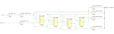
Post Synthesis Schematic from Xilinx Vivado:
The schematic looks quite simple, few flipflops connected in a sequence, along with some input and output buffers.
Hi Vipin,
ReplyDeleteThank you so much for this 4 bit counter coding.
Can you please help me out in coding part to count 0,1,3,4,6 and so on. Thanks in advance.
Regards,
Malarvizhi
I want some VHDL codes for my project Plzzz help me
ReplyDelete1.VHDL code for Priority generator using XOR as component structural
2.VHDL code for displaying 0 to 99 nos. on LED
3.VHDL code for SIPO & PISO with circuit diagram
4.VHDL code for Carry Lookahead Adder with circuit diagram
5.VHDL code for 16:1 Mux using 4:1 & 8:1 Mux as component structural style
6.VHDL code for Universal Shift Register