I want to share the VHDL code for a 3 to 8 decoder implemented using basic logic gates such as AND, OR etc.. The entity port has one 3-bit input and one 8-bit decoded output.

Only one bit in the output is high at any given time. And the index of the bit which is high at any given moment is decided by the value of encoded input. Since input is 3 bit, it can have a maximum of 8 (2^3) unique values, which correspond to the size of the output vector.
Circuit Diagram:
The circuit diagram for the decoder is given below. This diagram is taken from javatpoint. You can also see the truth table from the same website.
VHDL Code for 3:8 Decoder:
--libraries to be used are specified here
library ieee;
use ieee.std_logic_1164.all;

--entity declaration with port definitions
entity decoder_3to8 is
port(input : in std_logic_vector(2 downto 0);  --3 bit input
     output : out std_logic_vector(7 downto 0)  -- 8 bit decoded output
   );
end decoder_3to8;

architecture gate_level of decoder_3to8 is

begin

output(0) <= (not input(2)) and (not input(1)) and (not input(0));
output(1) <= (not input(2)) and (not input(1)) and input(0);
output(2) <= (not input(2)) and input(1) and (not input(0));
output(3) <= (not input(2)) and input(1) and input(0);
output(4) <= input(2) and (not input(1)) and (not input(0));
output(5) <= input(2) and (not input(1)) and input(0);
output(6) <= input(2) and input(1) and (not input(0));
output(7) <= input(2) and input(1) and input(0);

end gate_level;
A little tip on Concurrency in VHDL:
We have used basic logic gates here to implement the decoder. This is known as Gate Level Modelling in VHDL.
All the statements in the architecture body in the above code are concurrent, which means they execute parallelly. If you feel that the line order matters in the above code you can try changing them. But you would still get the same results in the simulation waveform.
Testbench code for 3:8 Decoder:
--library declarations
library ieee;
use ieee.std_logic_1164.all;

--this is how entity for your test bench code has to be declared.
entity testbench is
end testbench;

architecture behavior of testbench is

--signal declarations.
signal input : std_logic_vector(2 downto 0) := (others => '0');
signal output :  std_logic_vector(7 downto 0) := (others => '0');

begin

--entity instantiation with name association
uut : entity work.decoder_3to8
    port map(input => input,
        output => output);

--definition of simulation process
stimulus : process
begin
    --after changing 'input' wait for a bit to see the results in the simulation waveform
    input<="000";  --input = 0.
    wait for 2 ns;
    input<="001";   --input = 1.
    wait for 2 ns;
    input<="010";   --input = 2.
    wait for 2 ns;
    input<="011";   --input = 3.
    wait for 2 ns;
    input<="100";   --input = 4.
    wait for 2 ns;
    input<="101";   --input = 5.
    wait for 2 ns;
    input<="110";   --input = 6.
    wait for 2 ns;
    input<="111";   --input = 7.
    wait;  --wait indefinitely. simulation over.
end process stimulus;

end;
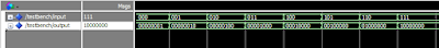
Simulation Waveform:
The codes were simulated in Modelsim. This is a screenshot of the waveform.
RTL Schematic:

Note :- Use RTL Viewer to get a closer look on how your design is actually implemented in hardware.
nice jobs...
ReplyDeletecan u plz give me a code for a 32 * 32 bit ram
ReplyDeletemy email id is smrutisoumya.mishra@gmail.com
the ram must hav 4 output ports each of 8 bit size
Can u plz explain me one program in detail. ........
ReplyDeletei need additive white gaussian noise vhdl code..plz help me
ReplyDeleteYou can find some logic gate templates in creately diagram community.
ReplyDelete